Welcome to our first post on Digital Design! We are glad that you found your way into this very exciting topic. In this post, we will try to give you an overview of the various aspects of digital design. For each topic, we will of course make a detailed and comprehensive post. This series intends to share our knowledge and experience in designing digital systems, such as microprocessors, with you. Unlike many other resources, we will start from the ground up and explain the basic principles behind many of the technologies in digital design in a simple way. So, if you’ve never heard of digital design before, this is the right place to start! And, if you are already an experienced student or engineer, you are also welcome, of course; maybe you might learn something new along the way. We also invite you (newbies + experienced) to give us feedback and ideas for future posts!
Now, let’s jump in, shall we?
If you look around you, you will probably find at least one electronic device near you. In fact, you are probably reading this post through one of those devices. Have you ever wondered, how such small devices which surround us every day, can do so much powerful things? For most people, their devices are just made up of “black magic”, and they “just work”. But if you have made it until this point, you are probably interested in what that “black magic” actually is, right? Then keep on reading and we will shed some light on this complex, but fascinating topic!
Microchips
All of our intelligent devices are powered by what are called microchips. You probably have heard that term before. A microchip (or just, chip) is a very tiny electronic circuit that can be integrated into other systems, to do some useful tasks for that system. There are a variety of chips designed specifically for certain tasks. For example:
- Measuring some state (e.g, temperature) of the system
- Controlling the system
- Processing data acquired by the system
- …
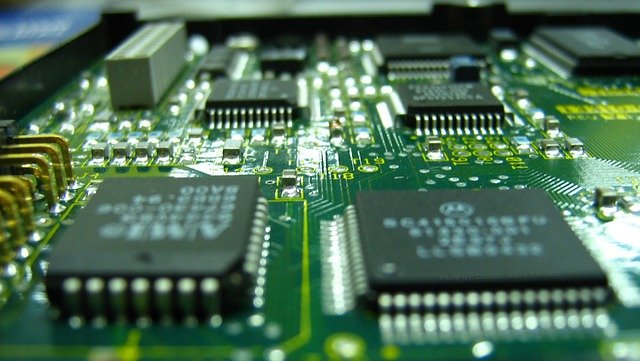
Maybe you have seen these black squares and rectangles that can be found all over circuit boards (such as the one shown below). These are all microchips!

Usually, a complex technical system consolidates multiple (10s to 100s) of different chips. Just look at a modern car: Nowadays, you can also think of a car as a supercomputer on four wheels. In a car, there are hundreds of different chips built into it. For example, there are chips that control the correct operation of the engine, others control the air conditioning and still others take care of the infotainment system. And things don’t stop here: with emerging technologies, such as autonomous driving, future cars will require even more, and more powerful chips.
Another example is your smartphone (which you might be holding in your hand right now). It also has several chips built into this what seems tiny space. It can be hard to imagine that modern smartphones are waaay more powerful than room-sized computers in the 60s or 70s (why this is the case we will see in a bit). Like in a car, there are also different chips for different tasks inside a smartphone. First of all, you have the CPU (central processing unit), which is like the brain of your smartphone. It essentially controls everything else to follow. You have specialized chips for doing network and radio processing to handle phone calls and mobile data, image processors to enhance the quality of the photos you take, controllers that regulate the charging of your phone, and many more…
Not only in our smartphones and cars we can find chips but also in areas such as
- Personal computing (PC, laptops, smartphones)
- Entertainment (TVs, radios, gaming consoles, …)
- Health care
- Industry/manufacturing
- Planes
- Rockets
- Mars rovers (yes, we even have chips on other planets!)
- …
We can probably continue that list endlessly. But you get the point: It’s hard to imagine modern society without microchips!
Ok, now you should have a broad understanding of what a microchip is and why they are so important nowadays. So your next question probably is: How are they made? This is where Digital Design comes into play. Digital design is a branch of electrical and computer engineering that focuses on the design of, well, you guessed it, microchips. Therefore, we also call it “Chip Design”. But before we dive into the design of chips, we first need to understand what a chip is actually made of.
Transistors

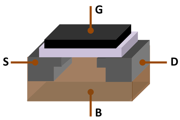
Let’s start from the foundations. A chip is nothing but a tiny electrical circuit. The fundamental building block that only made microchips possible is the transistor. Maybe you have heard about them before (processor marketing likes to include statements like “Our new processor has XY billion transistors!”). A transistor is nothing but a switch. However, unlike a mechanical switch, a transistor’s switching behavior can be controlled by some other current (or voltage). This allows the transistor to be much faster and smaller.
The first transistor was invented way back in 1947(!) and could be held in one hand. Since then the sizes of transistors have been shrinking - and they still do today. Modern chips contain billions of transistors. When you hear terms like “5nm CPU”, that means nothing but the size of one transistor on that chip (actually that is not entirely true, but that’s another story). So, transistors nowadays are only in the range of one billionth of a meter in size - just imagine: this means that modern transistors are over 10,000x smaller than a human hair! You might have heard about “Moore’s Law” before. The “law” was named after Intel co-founder Gordon Moore. In 1965, he predicted that the number of transistors in chips would double about every two years. And in fact, this exponential trend kept continuing for several decades, thanks to the advancements in transistor technology.

But what makes transistors so special for chips? As we said earlier, a transistor behaves like a switch. You probably know that any switch (eg, a light switch) can be either “on” or “off”, either “closed” or “open”, either “1” or “0”. (Maybe, in some reader’s heads, some bells started ringing, but if not that is totally fine, too - that’s why we created Bits&Volts :) This means a transistor can be in two states (on-off, 1-0). And this is also precisely the reason why computers “think” in 1s and 0s, or binary. However, one transistor on its own cannot do much useful work for us. We have to connect multiple such transistors to form more complex circuits, that then can perform the tasks we designed them for. But how do these circuits look like? These circuits are composed of so-called logic gates, which we will cover next.
Logic Gates

A logic gate is made up of a couple of transistors and has inputs and outputs. Each input can be either a “1” or “0”. A logic gate now produces a value at its outputs (for each output, either 1 or 0) based on what values are present at its inputs. There are different kind of logic gates. The most basic ones are AND, OR, and NOT gates. For instance, an AND gate has two inputs and one output. It produces a “1” at its output only when both of its inputs are set to “1”. Using the basic gates we can also construct other gates, such as XOR gates. We will cover logic gates in more detail in a later post, so don’t worry if you didn’t fully understand what’s going on.
The idea now is, to connect multiple of such logic gates to perform more complex logical operations. It turns out that we can describe most of the well-known mathematical functions and operations using logical operations. These logical operations have their foundation in the theory of Boolean Algebra. That now means, we can design logic circuits that can compute stuff. Well, there you have it: the processor inside a computer is nothing but that!
Now let’s see how we design such logic circuits.
EDA, HDLs and Testing
In the early days of microchips, the logic gate circuits were designed mostly by hand. This was kind of doable, because the number of transistors compared to today was much smaller, usually between 100s - 1000s. However, as the transistors were getting smaller and the chips more complex, engineers realized that designing those chips by hand would take a lot of time and was prone to errors. This was when the era of Electronic Design Automation (EDA) began. Engineers would now design their chips using so-called Hardware Description Languages (HDLs). These HDLs were inspired by programming languages used for writing software (however, writing software and writing digital hardware are two entirely different things!). The HDL code of the design is then translated into an equivalent logic gates description of the circuit by an EDA software tool. Again, this has some similarities with modern software design, where a compiler translates the higher-level code into assembly language for the CPU.
With the use of HDLs, the engineers didn’t need to focus on each and every transistor anymore and could put more time and effort into the actual design of their system. Two HDLs emerged in the 1980s: VHDL and Verilog. These are still the main languages to use when it comes to digital design. In the last couple of decades, new trends in digital design emerged, among which the most popular was High-Level Synthesis (HLS). The idea of HLS is to take an algorithm written in some high-level programming language, such as C, and automatically generate an optimized digital circuit for that particular algorithm. To this date, researchers all over the world are trying to come up with new languages and design paradigms with the hope of eventually replacing the traditional HDLs.
The rapid advancement of microchips over the past decades was - apart from the technological improvements in transistors - made possible by EDA. EDA tools automate many time-consuming tasks in chip design. Two of the most important tasks are Synthesis and Place & Route. In Synthesis, the HDL code is translated into a logic gates circuit (not a physical one, but described in some file). Then, in Place & Route, the EDA tool tries to find the optimal location for each gate on the final chip. Both tasks try to follow certain constraints given by the engineer, such as the final performance or power consumption of the chip. The tools use physical models of the actual gates to come up with estimations on performance or power consumption. The engineer can then analyze the results, and refine his design if he is not satisfied. We will show you how that’s done in practice in a later post in this series.
Another important aspect during the design of a digital circuit is testing. Before the chip is manufactured, we have to make sure that everything is working as intended. Consider this: When you ship software to a customer, and he/she finds a bug, you can easily patch it through a software update. However, what do you do when a customer finds a bug in your chip? How do we fix bugs in chips? The answer is: we don’t, because there is no such thing as a “hardware update” (some chips actually can be reconfigured, but we will cover them in a later post). Even if we could, doing this for potentially millions of sold chips, is straight-up infeasible. That’s why a LOT of time is put into testing before production. This is especially important for safety-critical applications such as planes or medical devices.
There are several ways to test a digital circuit. One method is simulation. In simulation, our HDL design files are read and test signals are applied to see whether the design behaves as intended. If an error is found during simulation, the designer analyzes the circuit and fixes the bug. Simulation is just one part of a whole sub-branch in digital design: Verification. Over the decades, with the rising complexity of chips, a lot of effort has been put into coming up with efficient verification methods. Simulation, as we saw above, is one of the more classical methods. Newer methods, such as formal verification try to mathematically prove that a circuit will work as intended.
Why verification is so important is also highlighted by Spectre and Meltdown. These were security vulnerabilities found in common processors, such as those from Intel or AMD. Even such big companies, with decades of experience, could not entirely verify their chips. And hardware bugs can be found years after the chips had been shipped. This shows how important verification becomes with growing chip complexity.
We have seen that EDA tools help designers lift most of the heavyweights in digital design. And that testing and verification are a big chunk of work in chip design. Next, let us see how a chip is then actually fabricated!
How is a chip manufactured?
Once the chip has been designed and verified, it is finally ready for manufacturing. What we didn’t tell you until this point is, out of what materials chips are made of. Let us answer that for you. A transistor is made mostly from semiconductors, such as Silicon. Only the special properties of semiconductors allow a transistor to behave like a tiny switch.

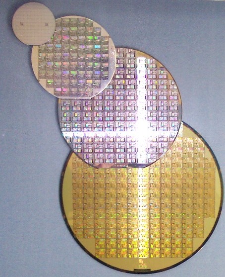
The entire manufacturing of a chip is a very complex and complicated process (“complex and complicated” is almost an understatement; it is one of the most sophisticated stuff we humans ever came up with!). The process consists of several steps. A plain Silicon wafer forms the base (also called substrate) on top of which the actual circuit will be built upon. We will spare you the details here, but basically, with each step, the transistors and their connections are more or less “printed” onto the wafer substrate. Because of their nature of being integrated into a Silicon wafer, chips are also called integrated circuits (IC) - this is contrary to “classical” circuits where the circuit is made up of discrete elements, such as resistors or capacitors.
Like the design, also the production of chips has been almost fully automatized. Because the process is very complex, it is a costly investment for a chip designer to maintain an own chip factory. Costs for such factories (which are also called foundries, or fabs) can easily go up into the billions. Therefore, a handful of companies in the world have specialized themselves in manufacturing microchips. A chip design company then just sends their final design files to one of the foundries for production. The foundry will then manufacture the chips and send them back to the design house. The manufacturing usually takes several months.
By the way, having only a few foundries across the world can become a significant bottleneck in the supply chain when the global demand for chips suddenly increases. This is also what we can currently (as of writing this article) observe during the chip shortage due to the Corona pandemic. Here is an interesting video by CNBC on this topic, if you are interested.
Wrap-up
Whew. There was a lot to take in probably, right? Let’s do a quick wrap-up of the main ideas we covered in this introductory post on digital design:
- Digital design deals with the design and implementation of microchips
- A microchip is a small electronic circuit, that is also called integrated circuit
- The fundamental building block of any microchip is the transistor
- A transistor is like a switch
- Using multiple transistors, we can construct logic gates
- Using multiple logic gates, we can construct complex circuits, such as processors
- Nowadays, digital design engineers use hardware description languages (HDLs) to design their circuits
- Modern chip design is nearly impossible without the help of Electronic Design Automation (EDA) tools
- The design is sent to a foundry for producing the actual chip
- The manufacturing of chips is a very sophisticated process
And that’s it! We hope you now have a better understanding of what goes into the development of these “black magic” containing black rectangles called microchips. In our next posts, we will cover the topics touched in this post in more detail, starting with transistors. Stay tuned!
Back to top ↑