Key Takeaways of this post:
- The Full-Adder (FA) is a combinational circuit which adds three 1-bit numbers
- In addition to the Half-adder, the FA has a third input, the Carry-In (Cin)
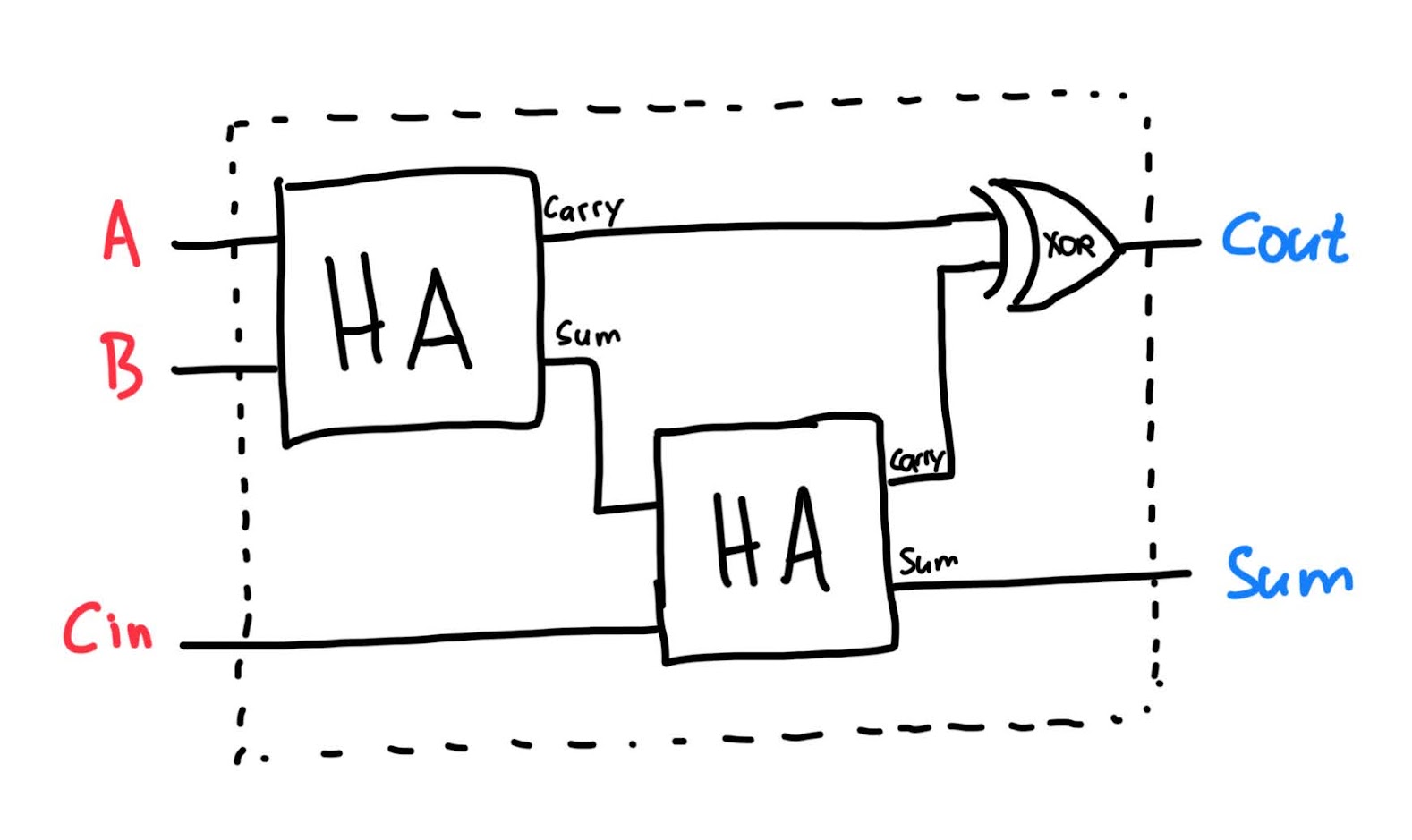
- A FA can be constructed using two HAs and an XOR gate
In our previous post, we have looked at the Half-Adder (HA), which is a combinational circuit used to add two 1-bit binary numbers. In this post, we will take a look at an extension of the Half-Adder, namely the Full-Adder (FA). The Full-Adder will allow us to construct larger adders. Let’s start with having a look at the FA’s circuit diagram:

As you can see, the FA consists of two Half-Adders. Like the HA, a FA takes in two bits (A and B). Additionally, there is a third input: the Carry-In (Cin). And like the HA, the FA produces two output bits, a Sum and a Carry-out (Cout). In a way, the FA is adding three 1-bit values. The Sum is the same as the sum output of the HA on the right, and the Cout is the XOR of the carries coming out of both HAs. The truth table of the FA looks as follows:
| A | B | Cin | Cout | Sum | |
|---|---|---|---|---|---|
| 0 | 0 | 0 | 0 | 0 | |
| 0 | 0 | 1 | 0 | 1 | |
| 0 | 1 | 0 | 0 | 1 | |
| 0 | 1 | 1 | 1 | 0 | |
| 1 | 0 | 0 | 0 | 1 | |
| 1 | 0 | 1 | 1 | 0 | |
| 1 | 1 | 0 | 1 | 0 | |
| 1 | 1 | 1 | 1 | 1 |
If you pay attention, you can see that the Cout and Sum bits combined represent the binary sum value of the three input bits: When only one of the input bits is a “1”, the combined sum is always “01”. When extacly two inputs are “1”, the sum is 2, or “10” in binary. And when all three input bits are “1”, i.e., the sum is 3, then we see “11” at the output.
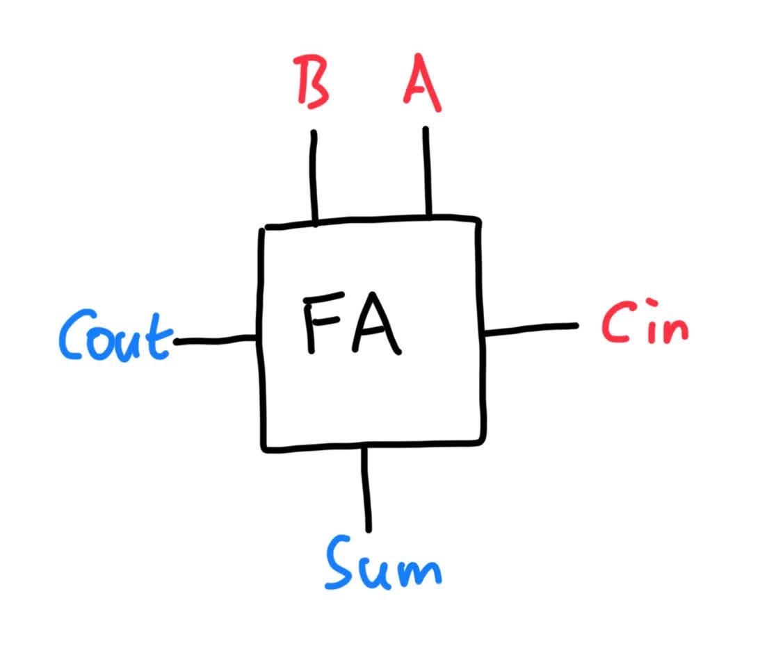
Just as with anything we have seen so far, we can abstract away the inner details of the FA by introducing the following schematic symbol:

Note that we have slightly rearranged the inputs (red) and the outputs (blue). This will become handy when we begin to combine multiple FAs to create larger adders. In the next post of this series, we will get to know our first adder circuit, the Carry-Ripple Adder. See you then!
Back to top ↑