In our last two posts, we have learned what logic gates are, which kinds of gates exist, and how they can be implemented using transistors.
Now it’s time to see what we can do with these things! Have you ever wondered why a computer is called “computer”? Well, as the name suggests, computers calculate, or compute things. What and how they do it is something we will cover in the future, but for now, we’ll focus on the essentials.
It turns out that we can use logic gates to do all kinds of mathematical operations. In this post, we will have a look at the most basic mathematical operation: the addition. How can we add two numbers using just simple logic gates, you ask?
Well, for that we need some basic understanding of binary numbers and how addition works in the binary system. As this blog series focuses more on the hardware side, we assume that you are already familiar with binary numbers. If not, or you need to refresh your memory, then feel free to consult a search engine and/or the latest AI of your choice to learn the basics about binary numbers. We recommend giving the Wikipedia article about binary numbers a read. Of course, there are also plenty of tutorials on YouTube, such as this one on the basics of binary numbers, followed by this one on doing addition in the binary system. We might also cover binary numbers in a future post in our Getting Started category, so stay tuned for that. Ok, do you know what binary numbers are and how to add them? Perfect! Then let’s see how we can build a circuit that can do binary addition.
To keep things simple, let’s first look at adding two 1-bit numbers. Recall, that, if both bits are 0 then the sum is 0, obviously. If one of the bits is 1 and the other is 0, then the sum is 1. And finally, if both bits are 1, then the sum will be 0 and we get a carry of 1. We can visualize this in a table form (calling the two bits “A” and “B”, respectively):
| A | B | Sum | Carry |
|---|---|---|---|
| 0 | 0 | 0 | 0 |
| 0 | 1 | 1 | 0 |
| 1 | 0 | 1 | 0 |
| 1 | 1 | 0 | 1 |
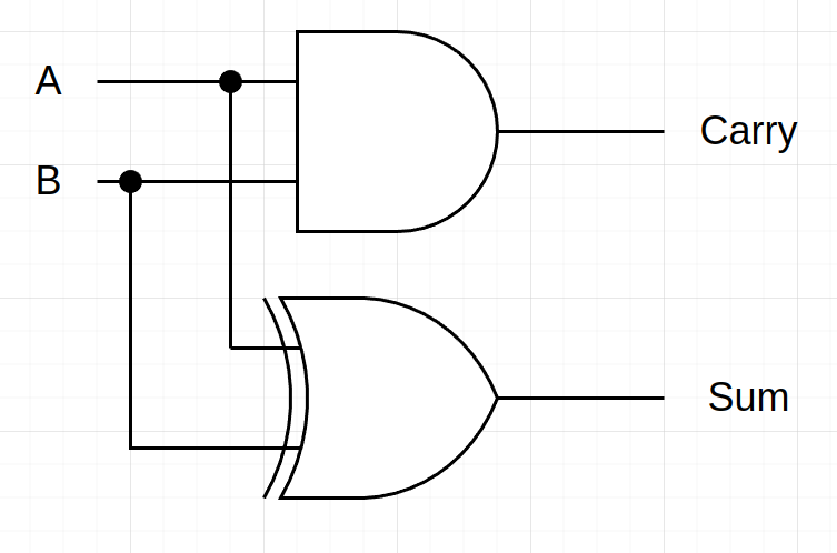
Do you notice something? Right, this looks like a logic gate truth table! And that’s precisely how we can come up with a logic circuit for adding two 1-bit numbers. This circuit has two inputs, the two numbers (or bits) A and B, and two outputs, the sum, and the carry. The corresponding circuit looks as follows:

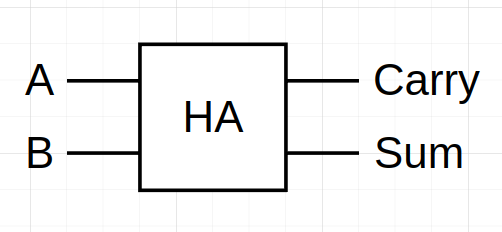
This circuit looks pretty simple, just one XOR gate whose output is the sum bit and an AND gate where the carry comes out. If you look at the truth table above, and remember what the truth tables of the AND and XOR gate look like, you can easily see why we need these two gates. This circuit is called Half-Adder. To not have to redraw all the gates when we are drawing many half-adders, engineers came up with a new symbol to depict a half-adder:

This is yet another example of abstraction: We simplify things by hiding the lower-level details of a particular system. In our case, the low-level details were the AND and XOR gates of the half-adder. And remember, those gates themselves again were an abstraction of the underlying transistor circuits!
You might think that now extending it to adding larger than 1-bit numbers is as simple as taking a bunch of half-adders for each digit, right? Well, almost. We need to extend our circuit a bit. Why? Because we also need to consider the carry bit coming from the previous digits (except for the first digits). The half-adder, as we saw, has no carry input, it only produces a carry output. By the way, “carry input” is also called “Cin” (spell “see in”) and analogously “carry output” is called “Cout”. This is useful in circuit diagrams, so we don’t have to write much (remember? Engineers are lazy ;) The extension to the half-adder is called Full-Adder and has an additional carry input. We will cover the full-adder in the next post.
For the curious ones: Try to draw the transistor diagram of the half-Adder (if you’ve read our last posts, then this shouldn’t be too hard)! Also, one more thing: Whenever we hook up a bunch of logic gates together, the resulting circuits are referred to as combinational circuits. In digital design, there is another important class of circuits, the sequential circuits, which we will see in the future.
For now, we hope you got a basic understanding of how the half-adder works! Let’s summarize what we’ve learned. The half-adder…:
- … adds together two individual bits
- … produces a sum bit and a carry bit as outputs
- … is constructed using one AND gate and one XOR gate
As always, give us a follow on Twitter to not miss any future posts! See you next time!
Back to top ↑