In our last post, we introduced you to what goes into the making of microchips. If you haven’t read that post yet, feel free to read it first, then come back to this post again. In this post, we will cover the basics of the fundamental building block of any chip out there: the transistor.
As we already briefly touched in our previous post, a transistor is nothing but an electrically controlled switch. The fact that their switching behavior can be controlled electrically, makes them very fast compared to mechanical switches, such as the light switch in your room. And, additionally, transistors can be made extremely tiny in size, making it possible to fit billions of them on a single, fingernail-sized microchip! How do they work, you ask? Well, let’s find out!
A Transistor is a Faucet for Electrons
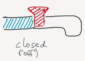
Let us approach this by using the best way of explaining complex things: analogies! The basic concept of transistors can be explained with a water analogy. You can think of a transistor as a water faucet (essentially a faucet is also nothing but a switch for water), as shown in the following picture. In the picture, the faucet is closed (or “off”):
When we open the faucet, water is allowed to pass through and exit at the end of the faucet:
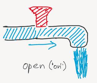
This is the “on” state of the faucet.
A transistor works just like our faucet example. Of course, there is no water in electric circuits. The flow that we are controlling with a transistor is the flow of electrons, or in other words, the electric current.
The following picture shows the schematic symbol of a transistor (we use this symbol to represent transistors in electric circuit diagrams):
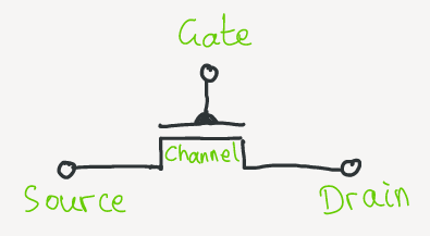
A transistor is a three-terminal device, i.e., it has three pins that we can connect other wires/devices to. The terminals are called the gate, source, and drain. Current can flow from source to drain through the part called “channel”. The gate contact can control this current: if there is no voltage present at the gate, the channel is closed, and no current flows; the transistor is off. When we apply a certain voltage at the gate terminal, the channel opens, and a current can flow from source to drain; the transistor is on.
Now, let’s see how transistors and pipes are related:
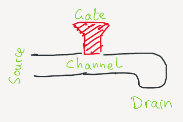
The water flows from the “source” to the “drain” through the “channel”. The “gate”, in this case, is simply the valve of the faucet.
Here you have it: A transistor is basically a tiny faucet to control the flow of electrons! Unlike a real faucet, which can be opened in one quarter, one half, and so on, we operate transistors in only two states1: ON or OFF. Because engineers are lazy, we like to abbreviate the states with 1 and 0, respectively. And this is precisely the reason why computers “think” in 1s and 0s (also called binary)! We will uncover the secrets of how this thinking actually works in our upcoming posts.
Next, let us have a look at a concrete type of transistor.
The MOSFET
There are two types of transistors out there. One is the field-effect transistor, or FET, and the other one is the bipolar transistor. Both types have the same goal, namely to control the flow of some current. However, even though both are semiconductor devices, they work based on different principles. This makes each of them useful in special application areas. As nowadays in digital microchips solely FETs are used, we will focus our discussion on them for now.
Let’s look at the most basic FET: the MOSFET. Its name stands for metal-oxide-semiconductor field-effect transistor. The next picture shows a cross-section of a MOSFET:
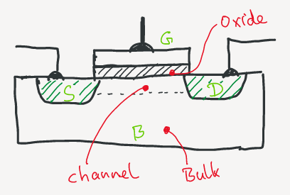
You might have noticed the same three terminals (gate, source, and drain) we introduced earlier, this time with their common abbreviations (G, S, D), as they are used by engineers. “B” stands for bulk (sometimes also called body or substrate). The bulk is basically the basis on top of which the transistor is built (if you remember from the previous post this basis is nothing but the actual wafer). Bulk, source, and drain are made from silicon. The gate on the top can theoretically be made of any metal, usually, poly-silicon is used today. Between the gate “plate” and the rest of the transistor, we can see another layer called oxide. The role of this oxide layer is to be an insulating layer so that no current can flow between the gate and the bulk (or source/drain).
When we apply a voltage at the gate terminal, a conducting channel starts to form between the source and the drain. This channel then allows electrons to flow from source to drain. The voltage we need to apply to the gate such that the channel opens and a current can flow between source and drain, has a special name: threshold voltage. For any gate voltage below the threshold voltage, the transistor will not let any current pass from source to drain. The threshold voltage is commonly abbreviated as $V_{th}$.
Let’s see what goes on inside a transistor.
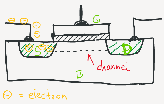
When there is no voltage present at the gate, the channel between source and drain is not conductive, i.e., no current can flow from source to drain. The MOSFET is switched off. The following picture depicts this state (notice how the electrons are waiting at the source terminal):
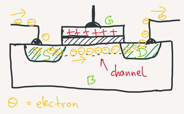
When we now start applying a positive voltage at the gate terminal, the gate will attract electrons from the source terminal (remember that the source is made from Silicon which has some free electrons). As we increase the gate voltage, more and more electrons from the source will accumulate near the gate (the area where the channel is supposed to be). Note that the electrons actually would love to get to the positively charged gate, but they can’t because of the insulating oxide layer between gate and bulk. When the gate voltage reaches the threshold voltage, there are now enough electrons in the channel area to allow a current flow between source and drain. Imagine the accumulated electrons in the channel as a “bridge” between source and drain. Now electrons can flow from source to drain; the MOSFET is switched on:
Don’t worry if all that sounded too complicated. It was to us too, when we learned this the first time! As we will point out later in this post, it is not necessary to remember all the nitty-gritty details (even we do not).
One more thing. There are two types of MOSFETs. The one we presented you above is also referred to as NMOS. The other MOSFET type is called PMOS. The difference between the two is that the PMOS has the opposite behavior of an NMOS: when there is no gate voltage, the PMOS is switched on, and a positive gate voltage switches off the PMOS. We will spare you further details here2, but for now, it’s sufficient to know that there are these two types of MOSFETs, and they essentially work opposite to each other. In digital systems, we need both NMOS and PMOS to build complex circuits.
We hope that by now, you have a broad understanding of how transistors work. If you want to see a more visual explanation and maybe also understand the more low-level details of how MOSFETs work (e.g., why we have to “dope” Silicon to enhance its conductivity), check out this great video by Veritasium. Another good explanatory video with animations is this one.
It shall be noted that even though it is helpful (and sometimes necessary) to understand the detailed working of transistors, in many practical situations, especially when designing digital circuits, it is often enough to just know that transistors can be in two states, on or off. This is one example of an abstraction, where we basically ignore the low-level details and just focus on the essentials. We will find many of these abstractions throughout digital design.
Next, we’ll conclude this post with a short wrap-up!
Wrap-up
Let’s summarize what we’ve learned in this post.
- A transistor is an electronic device to control the flow of current.
- There are two major types of transistors: bipolar and field-effect transistors.
- In digital circuits, field-effect transistors, such as the MOSFET are used.
- MOSFET stands for metal-oxide-semiconductor field-effect transistor.
- A MOSFET has three terminals: gate, source, and drain.
- A voltage at the gate can control current flow between source and drain.
- There are two types of MOSFETS: NMOS and PMOS.
- In digital circuits, transistors are used as switches.
- A transistor switch can be off or on, hence modern computers only “understand” binary (0/1).
In our next posts, we will learn how transistors can be used to design complex digital circuits! And, as always, we will keep you updated on Twitter. See you then!
-
Actually, transistors can also be “half-open”. However, this operating mode is out of interest in digital systems. If you are curious: transistors operated in states between “fully off” and “fully on” are commonly found in analog circuits, such as amplifiers. ↩
-
For the curious ones: it has to do with the so-called majority charge carriers. In NMOS devices, these are the electrons (as we saw earlier), and in PMOS devices the majority carriers are positively charged holes (have a look at this video by Veritasium, he explains nicely what holes are). ↩